Monday, 13 December 2010

The Input/Output Panel (P1, P2)

The Input/Output panel on the computer is the section which most of the hardware needed by the user connects to. The picture labels each of the ports, and after there is a description each.
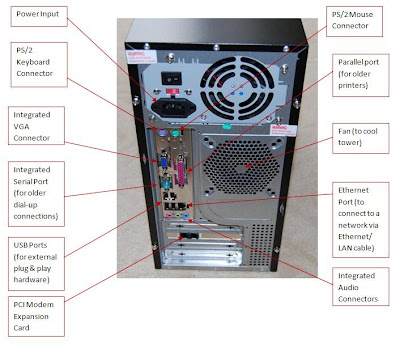

A computer with labelled ports


·         The Power Input is the section on the power supply (PSU) which the 12v Kettle lead connects to. This cable provides power to the computer.
·         The PS/2 Keyboard connector is where the keyboard connects to the motherboard. This is normally found next to the PS/2 Mouse connector.
·         The integrated VGA connector is where the monitor is connected to the computer. This is a basic graphics card which processes the connection between computer and monitor.
·         The integrated serial port is used by older dial-up modems to gain an internet connection to the computer through the modem.
·         The USB Ports are used by modern devices to connect hardware to the computer. Most new devices have a USB interface as they are globally universal.
·         The PCI Modem expansion card allows for a connection to the internet without a modem. This connects straight to the phone line to gain access to the internet.
·         The PS/2 Mouse connector is where the mouse plugs into the motherboard for use by the user.
·         The parallel port is used by older printers to connect to the computer.
·         The fan blows the air in and out of the tower as to cool all of the computer components. This connects straight to the motherboard internally.
·         The Ethernet port is used to connect a computer to a LAN or WAN by setting it an IP address within the network.
·         The integrated Audio panel allows connections to microphones, speakers and headphones to play or record music.


The Storage Media (P1, P2)

The storage media of a computer is the part which actually holds the data required to load the operating system and other software. The storage media holds data after the computer has been turned off, or after it has been removed from the computer itself. The main type of storage media is the hard drive, which houses the files of the operating system, software and user saved data.

An example of an IDE Hard Drive


Traditionally, hard drives are connected using 40-pin 80-conductor ribbon data cables, which run between the hard drive itself and the motherboard. Using an IDE (Integrated Drive Electronic) connection, the hard drive connects to the motherboards data paths (Buses) which allows for data to be saved to the device. Each of the IDE ribbons can hold two devices (known as a master and a slave). The master drive handles all of the connections, and sends only the requested ones to the slave drive. The slave only sees what the master has sent it.

A IDE Connector

Other storage devices can be removable such as USB drives, CD/DVDs, SD Cards and even legacy floppy drives. The computer reads these drives as external, and they are normally only used to carry user created data from one device to another. For example, the SD Cards normally hold all the images taken on a digital camera and allow the computer to access the photos. Other drives can be static such as external hard drives, but yet again these are traditionally only used for user file storage and rarely hold the operating system or software.


An SD Memory Card

A USB Memory Card


Thursday, 9 December 2010

The Power Supply (PSU) (P1, P2)

The PSU (Power Supply Unit) is the box which the power cable connects to on the I/O (input/output) panel. All of the power to the motherboard and other hardware comes from this supply. The two types of power supply are…
  • AC – Alternating current
n  The direction of the current alternates providing an efficient way of providing power over long distances
  • DC – Direct current
n  The power runs from negative charge to positive charge, always in the same direction. Good for short distances
A typical power supply

Externally, the plug socket provides the PSU with 110-115V AC current. The PSU then coverts the AC to DC and sends the required voltage to each individual piece of hardware (either 5V or 12V). The PSU gives out all of the different voltages using different connectors for each piece of hardware. They are as follows…
·         P1
o   Provides motherboard with power
o   20 or 24 pins
o   This connector is the largest of all the connectors
·         P4
o   ATX12V 4-pin power connector
o   Connects to motherboard to supply dedicated power to the processor
o   High end motherboards and processors need more power, EPS12V , and therefore have an 8 pin connector
·         4-pin Peripheral
o   Smaller connectors that go to the various disk drives of the computer
o   Four wires
o   two black both ground
o   one red +5V
o   one yellow +12V
·         Mini-connector
o   One of the smallest connectors
o   Supplies the floppy drive
o   Can be used as an auxiliary connector for AGP video cards
o   Configured similar to 4-pin Peripheral connector
·         Auxiliary power
o   There are several types of auxiliary connectors designed to provide additional power if it is needed
·         Serial ATA
o   15-pin connector for components which use SATA power plugs
o   supplies power at three different voltages
o   +3.3V
o   +5V
o   +12V
·         6-pin
o   Generally used for PCI Express graphics cards
o   Can output a maximum of 75 W
·         6-pin + 2
o   Allows for backwards compatibility
o   PCI Express graphics cards
o   6 or 8 pin can be connected with this connector
·         C14 IEC connector
o   “The kettle lead connector”


This shows a typical connectors on a PSU


The Expansion Cards and Ports (P1, P2)

There are many ports and expansion cards available, all of which are provided to help anyone upgrade their computer as easily as possible. The main two types of specialist ports are for networking interface cards and graphics cards. There are three main types of port which are incorporated onto modern motherboards, which are…
·         AGP (A legacy Graphics Card adapter)
·         PCI (Used on most expansion cards)
·         PCI-Express (Used mainly for modern Graphics Cards)

An example of a PCI Card (This one is a USB Expansion Card)

Expansion cards can be used to add a wide range of hardware devices to a computer. All of the following are hardware expansions which can be added using the expansion cards…
  • Video cards
  • Audio codec
  • Sound cards
  • Network cards
  • TV tuner cards
  • Video processing expansion cards
  • Modems
  • Radio tuner cards
  • Security device cards
  • Interface adapter cards, including parallel port cards, serial port cards, multi-I/O cards, USB port cards, and proprietary interface cards.
Inserting a new expansion card is simple, quick and effective. It can allow a user to do so much more with their computer. Here is a guide of how to install a new network card. To start, you will need the following equipment:
·         Non-magnetic Philips screw driver
·         The card you wish to install on the system (out of box and ready to insert)
·         A method of organising the replaced screws.

To install the card, follow these instructions:
1.   Make sure that the computer and you are earthed, as to not damage any of the equipment.

2.   Remove the outer casing of the chassis, by unscrewing the 2 screws on the back of the computer. Place the screws somewhere safe and the casing out of the way.

3.   Identify a spare port on the motherboard, ensuring it is the correct type for the card you wish to install (e.g. a PCI-Express port for a PCI-Express Card).

4.   Remove the metal bar which covers the spare port’s opening to the outside of the case. It should look something like this…


A spare port on a computer motherboard

5.   Gently push into place the card you are installing, ensuring not to force anything as this could result in damage of equipment.

6.   Place a screw (normally given with the card) through the outer chassis to hold secure the card in place. This will ensure the card does not come loose, and should look similar to this…

The screw which secures the expansion card
7.   Replace the outer casing of the chassis and screw the case to the main frame of the chassis.

8.   Turn the computer on and install the drivers for the device.

Done, the device should now be working.

The Memory (P1, P2)

Memory is the part of the computer in which data is stored. The main type of memory is Cache. This is the memory which is used by frequently used data. It can only be used for temporary storage of data as this allows for faster access. The Internal Cache is located in the processor and is categorised by proximity to CPU L1 (in the CPU) and L2 (could be internal or external). External Cache is also on the motherboard but is not built into the processor chip. The Cache holds the data that the processor uses a lot, and acts as a buffer for the CPU. The Cache guesses what the processor will need to use next (judging by previous command patterns) and prepares the file for use.
An example of RAM
Internal Memory is used to store the programs that are currently being run on the computer. It is also used to store the data that the program works on, as to help towards having a quicker system.
There are many different types of actual memory. They are as follows…
·         Volatile
o   DRAM – Dynamic RAM
o   SRAM – Static RAM
·         Non-Volatile
o   ROM
§  PROM
§  EPROM
§  EEPROM
o   Flash
Volatile is Random Access Memory which can be written to. It can also be read from but it looses its power when the computer is turned off. The volatile RAM is measured in bytes, megabytes and gigabytes. The more RAM that is installed on the system, the more instructions can be held meaning that there is less time spent swapping information in and out of RAM.
An example of RAM
The difference between DRAM and SRAM is that DRAM is made up of capacitors, while the SRAM is made from transistors.  The transistors do not need to refresh as frequently but it tends to be more expensive than DRAM.
The non-volatile memory is Read Only Memory which keeps the information which is written on it when the computer is turned off. It is used to store the firmware for devices along with the BIOS. The three main types of ROM are PROM, EPROM, and EEPROM.

Wednesday, 8 December 2010

The Motherboard (P1, P2)

The Motherboard is the central PCB (Printer Circuit Board) which homes and connects all of the computer’s hardware together. They come in many different types such as:
·         ATX – The currently used type
o   Designed for easy access
o   Improved cooling due to layout
o   Consolidating I/O Panel (Input/Output)
o   Controls the power supply direct.  
·         Baby AT/ LPX – Used in legacy IBM machines and no longer available.
There are many components which build a motherboard, and all of which are necessary in modern computers. They are:
o   Chipsets
§  North Bridge
§  South Bridge
§  BIOS Chip
o   CPU slot
§  CPU (Processor)
§  Heat sink
o   Voltage Regulator Module
§  This provides the microprocessors with the correct supply voltage
o   Memory slots
§  RAM (Random Access Memory)
·         DRAM (Dynamic)
·         SRAM (Static)
§  ROM – (Read Only Memory)
o   Expansion bus slots
§  AGP (Accelerated Graphics Port)
§  PCI (Peripheral Component Interconnect)
o   Battery
§  CMOS Battery
o   Slots for storage devices
§  SATA (Serial AT Attachment)
§  IDE (Integrated Drive Electronics)
o   Connectors
§  12v Power connector
§  CPU fan connector
§  ATX Power connector
§  Chassis Fan
§  Internal Audio
o   Headers
§  System Panel
§  Game Port
§  Chassis Speaker
§  USB 2.0
§  COM Port
§  Front Panel Audio
§  Shared USB 2.0


A Basic Motherboard